
Umbrella Master
Dev Log #2 - Umbrella Maker: Building the Hardware
Hello everyone! Today, we’re diving deep into the true core and soul of this game—the unique, custom-made umbrella controller we built ourselves! We’ll cover how we gradually upgraded and designed our controller from the prototype stage to the final version. If you ever get the chance to build your own umbrella controller for fun, this could be a great reference. (Will anyone actually try this?)
Prototype
What kind of umbrella to make?
After settling on the game’s concept, we started designing our controller. First, the main body naturally had to be an umbrella. Second, based on the gameplay, we needed to detect three core actions:
- Swinging: Requires capturing fast movements and pose changes.
- Shooting: Needs a trigger-like input.
- Opening the umbrella: Needs to detect the open state of the canopy.
To meet these requirements, we find solutions one by one.
- Pose Sensing: A gyroscope would be excellent. We could directly replicate the real umbrella’s pose in the game using rotational pose data. This would allow swing detection based on the 3D model’s movement.
- Trigger Button: Instead of a simple button, we chose a joystick. It offers some travel distance, feeling more like pulling a trigger. Early on, we also added dodging and calibration functions to the joystick.
- Opening Detection: We considered many implementation methods and finally decided to place an IMU on the canopy as well. By calculating the angle between the two IMUs, we could determine the umbrella’s open/closed state.
- To connect all the components, we used an ESP32. Finally, all data was packaged in a specific format and output directly via the serial port. In the Unity engine, we used the Ardity plugin to conveniently read the serial data.
The first… controller
Before formally designing the handle, we quickly built a minimal prototype on a breadboard, connecting the IMU and ESP32, to initially test the pose tracking algorithm and the hardware/software communication.
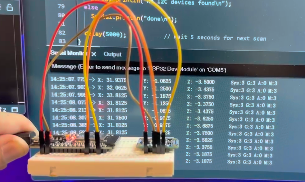 ↑ The very beginning
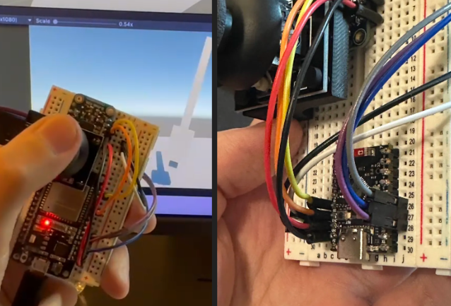 ↑ Added the joystick and switched to a smaller ESP32 to fit inside the umbrella
Integrating with the umbrella
Then the next question was, how do we put all this stuff onto the umbrella?
After much thought, the most suitable location seemed to be the handle. The best approach was to remove the original handle and replace it with one I designed myself, containing all the components. I referenced the dimensions of an umbrella I often use and designed an extended handle using Fusion 360, leaving space to accommodate the electronic components.
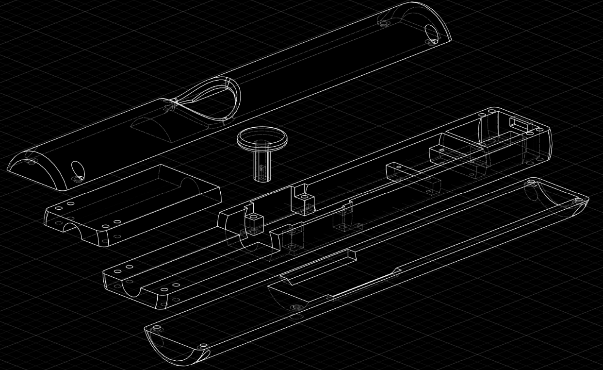 ↑ First version of the umbrella design
You can see we hollowed out the inside of a cylinder, split it into three parts, with the middle section being the primary location for components. We designed precisely positioned baffles and screw holes to secure our parts, leaving a structure at the top for connecting to the umbrella shaft. Here, hot glue was used to connect the original umbrella shaft and our handle. Finally, the top and bottom parts form a rounded exterior, with space reserved for the joystick. The joystick cap was also designed and printed by us.
After some time spent on model adjustments and 3D printing, the first custom handle was born! Then came assembly and soldering. Since the space was quite tight and the soldering iron could easily melt our handle, this step required extreme caution.
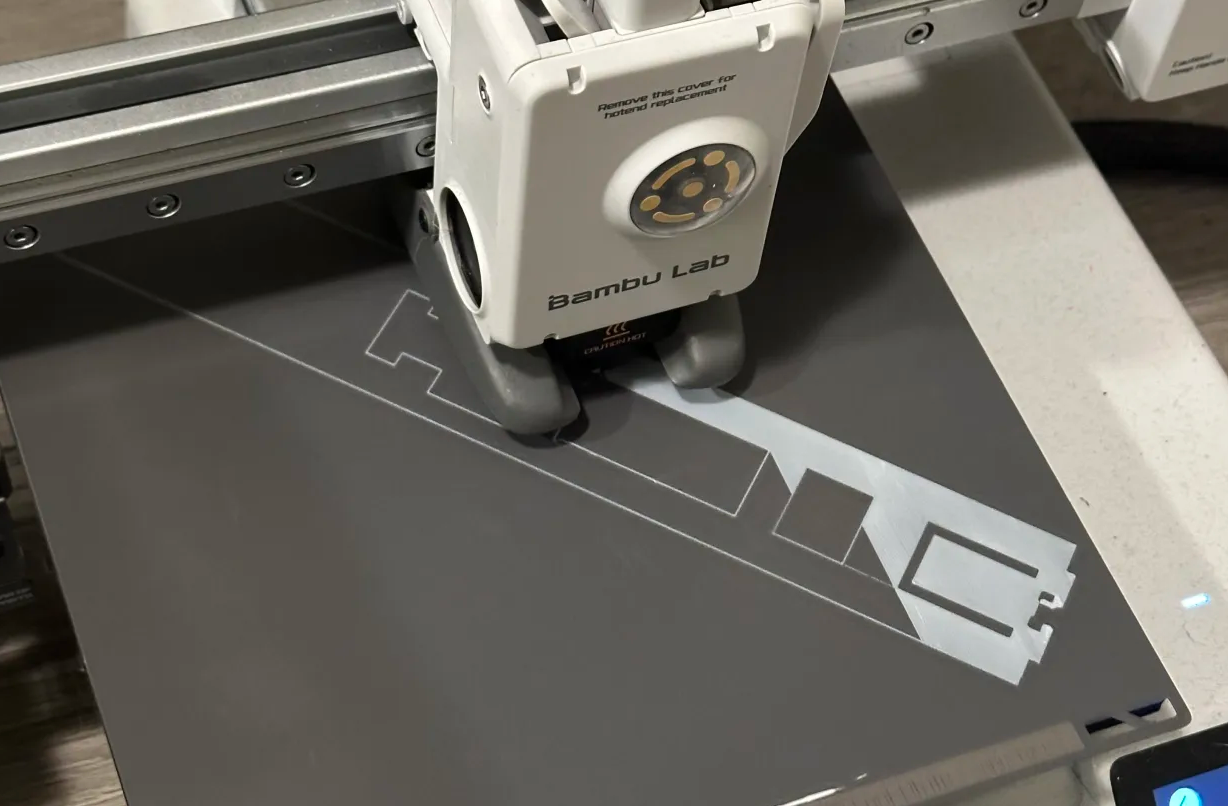 ↑ Printing the handle…
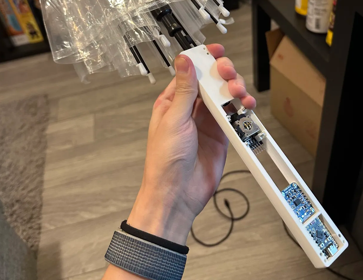 ↑ Testing component placement, putting it together with the umbrella
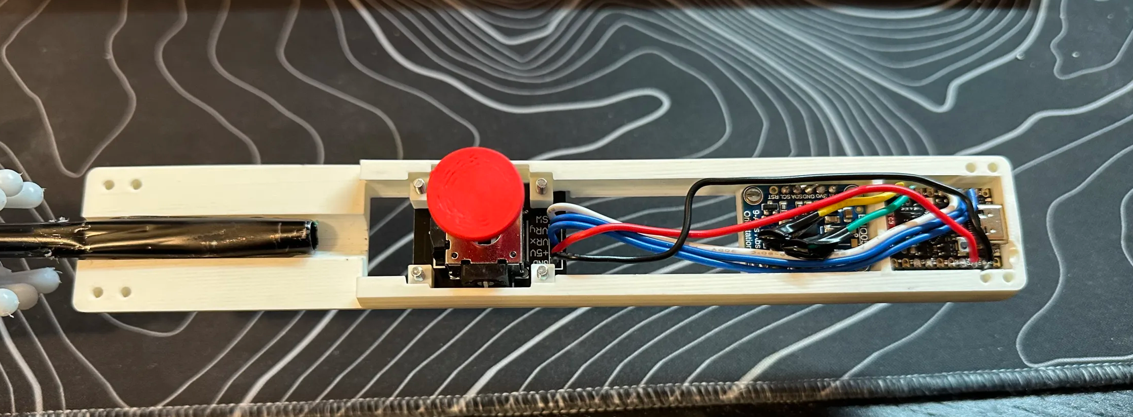 ↑ Some soldering done
After the first assembly, when I plugged it in to test, the entire umbrella didn’t respond at all! The ESP32 had no output, and the sensors couldn’t be read. I nearly broke down, thinking I had soldered something wrong. After careful investigation, the problem turned out to be the wires connecting to the IMU at the top of the umbrella. To run the power lines (VCC, GND) and I2C data lines (SDA, SCL) from the handle through the shaft to the top, the cables were pulled too long. Being a hardware novice, I didn’t know why, but based on my tests and online advice, I2C might indeed work better over shorter distances. Ultimately, I decided on an ESP-NOW wireless relay solution, a somewhat roundabout approach, but it worked: only power lines ran up from the handle. An additional ESP32 was added at the top, solely responsible for reading the top IMU’s data and wirelessly transmitting it back to the main ESP32 in the handle via the ESP-NOW protocol. This way, all data was aggregated in the main ESP32 and then uniformly transmitted to the computer via USB cable. Problem solved!
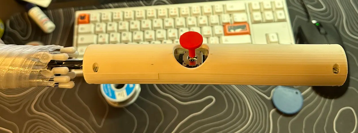 ↑ The handle
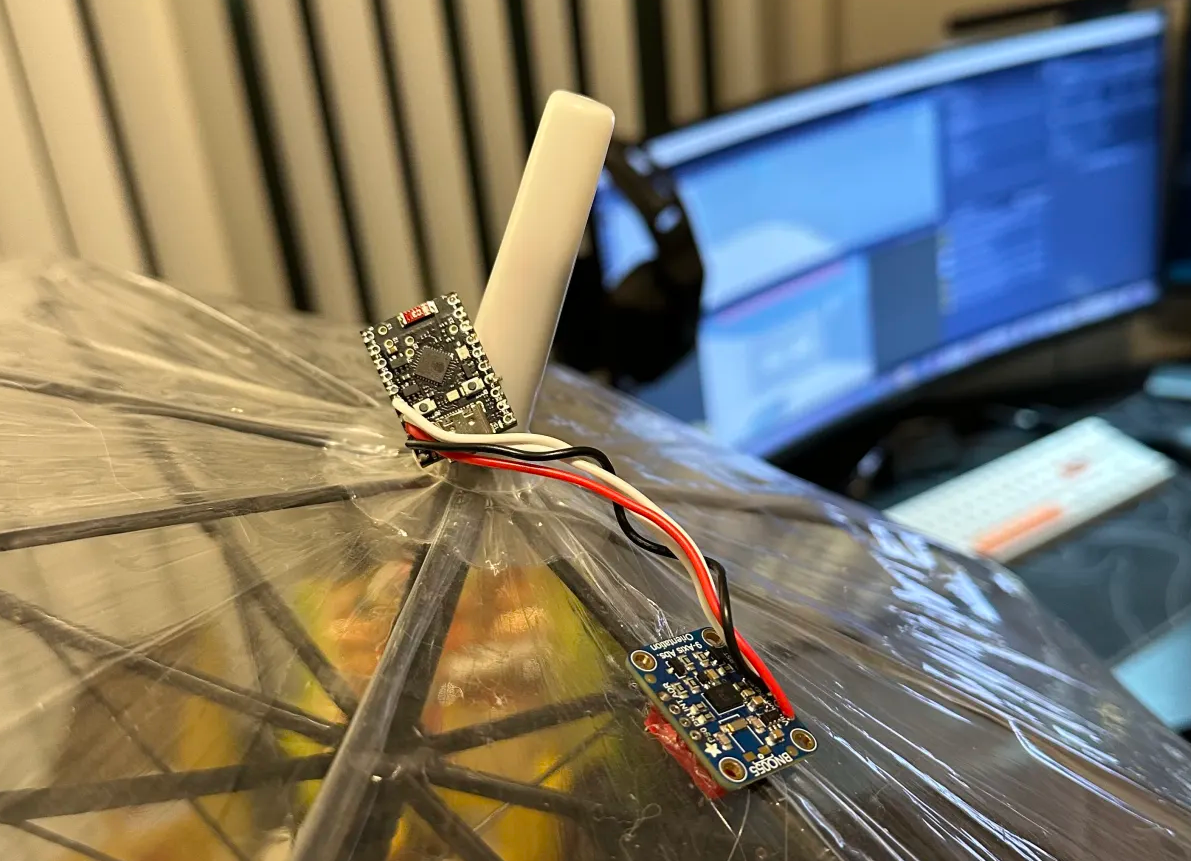 ↑ And the sensor on the canopy
This was our first version controller. And it actually worked.
Upgrade! 2.0!
Preparing for the upgrade
After the prototype phase, we identified the shortcomings of V1 and the future direction:
- First, get rid of the cable. Although we provided a very long cable, it would be much better if the umbrella were wireless.
- Second, add feedback. We wanted to add vibration motors to enhance the sense of impact and interaction experience.
- Finally, a challenge: spatial tracking. Our professor proposed a bold idea: since using the umbrella is very natural and everyone knows how, but pushing the joystick left and right isn’t quite as intuitive here, could we ditch joystick dodging and have the player physically move their body to avoid attacks?
To achieve these goals, we needed to add some new hardware to our umbrella:
- Battery power
- Vibration motors
- Ultra-Wideband (UWB) positioning chips: To achieve precise indoor spatial positioning, we chose UWB technology after research. It calculates distance by measuring the time of flight of radio signals over extremely short intervals, offering high precision (at least, that’s how it’s advertised, though the data fluctuated quite a bit in practice, possibly due to my implementation). We opted for Makerfabs’ ESP32 + UWB integrated modules. The system requires at least three points (two fixed Anchors, one mobile Tag) for triangulation.
So, should we keep the joystick? The answer is yes, we still need a trigger. We could simply restrict the joystick’s left-right movement with the case design.
The new handle
Naturally, we faced a new design challenge: put all the new components into the umbrella!
The newly added battery, UWB module, etc., were quite large, but my 3D printer’s size was limited. The handle couldn’t be made longer, only slightly larger in diameter. What followed was a long cycle of 3D modeling, print verification, adjustments, and re-printing. How to reasonably lay out all components, battery, wiring within the extremely limited space, while also considering the feasibility of actual installation and soldering, was a huge challenge for me as a 3D modeling beginner. Ultimately, our design looked like this:
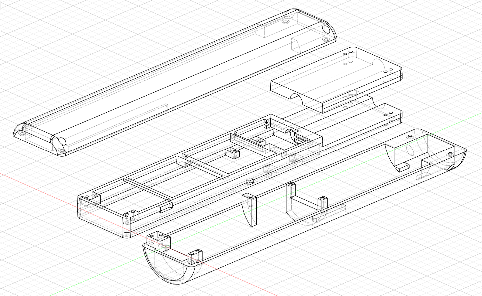
You’ll notice the overall structure is similar to our initial design, but the entire handle is thicker. To maintain a decent grip, the top section was flattened. The bottom is primarily reserved for installing the battery module, with the new UWB chip stacked above it. The joystick still occupies the middle position of the handle, with the ESP32 and gyroscope stacked above it. Finally, both the upper and lower shells have slots designed for the vibration motors to snap into. The connection part with the umbrella shaft remains the same as before. Considering strength, we ultimately chose PLA-CF material for printing the final handle, significantly improving the shell’s strength and rigidity.
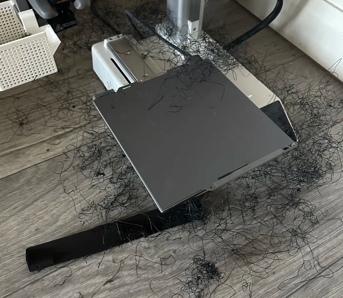 ↑ Also significantly increased the chance of print failures
However, even with careful design, the final assembly process was still extremely painful because the reserved space was incredibly tight. Some component mounting designs pushed the limits of how many objects a single screw could secure. The most impressive screw simultaneously held the battery, the UWB chip, the mid-frame, and the bottom shell. In short, I never want to assemble it a second time.

↑ This is a GIF of the assembly process, click to play
Detailed Information
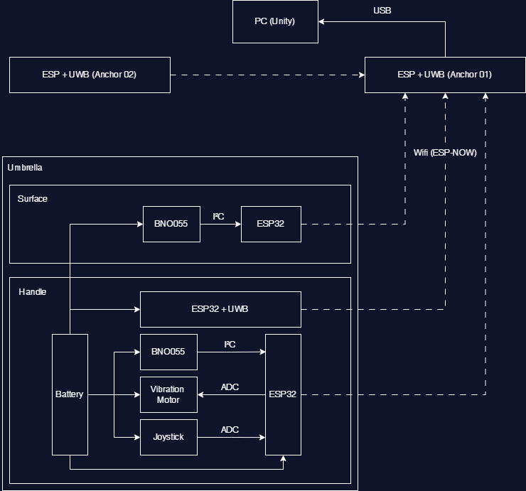
That covers our design thinking and process. Now let’s take a closer look at the internal composition and workflow of the V2 controller:
-
Hardware List:
- Canopy: 1x ESP32 C6 Supermini + 1x BNO055 IMU
- Inside Handle: 1x ESP32 C6 Supermini + 1x BNO055 IMU + 1x Joystick + 1x Makerfabs ESP32 UWB module (Tag) + 1x Battery & Charging Module
- Positioning Anchors: 2x Makerfabs ESP32 UWB modules. One connected to computer USB for power and serves as data receiver (with an extra small screen for debug info); the other battery-powered and placed wirelessly.
-
Data Flow:
- Software Implementation:
- Controller Firmware (ESP32 side): Mainly responsible for initializing sensors, reading data, and sending it via ESP-NOW to the receiver.
- Hardware-related logic in the game (Unity side):
- Data Processing: Convert all strings read from the serial port into corresponding stored variables.
- Pose Synchronization: Parse the pose information from the handle’s BNO055 data to synchronize the in-game umbrella in real-time.
- Swing Detection: Create a virtual point at the tip of the in-game umbrella. Determine if it’s a valid swing by calculating if the distance moved by this point within a short time (e.g., 0.1 seconds) exceeds a threshold. If yes, generate corresponding effects based on the swing’s start and end points.
- Shooting: Directly read the forward/backward axis output value of the joystick. We restricted the joystick to only move forward and backward via the shell structure, making it feel more like a trigger with travel distance.
- Open Detection: Calculate the relative angle between the two BNO055s based on their pose data. Measure data when the umbrella is closed and open as references to determine the current opening percentage.
- Movement Tracking: Unity gets the distances d1, d2 from the UWB Tag to the two Anchors, along with the fixed distance D set between the two Anchors. Using trigonometry, calculate the two angles of the triangle formed by the player’s Tag and the two Anchors. Set thresholds; if a specific angle is exceeded, it counts as movement.
Experience
So, how did this V2 controller, into which we poured our hearts and souls, perform?
- Highlights:
- Responsiveness and accuracy were satisfactory in most cases, and the wireless experience is great.
- UWB positioning indeed made it possible for players to interact through body movement.
- The joystick trigger feels good.
- Shortcomings:
- Stability issues: This is currently the biggest pain point. There’s enough material about this for another whole article.
- Battery: Due to volume constraints, we couldn’t implement a replaceable battery structure in the end; it can only be charged via the reserved charging port. (And battery life hasn’t been fully tested but doesn’t seem very durable).
Finally
Building the umbrella for Umbrella Master has been a journey full of challenges, failures, learning, and breakthroughs. It’s far from perfect, with many areas needing improvement. But it’s precisely these imperfections and the effort we put in that make it unique. Even if it doesn’t end up working perfectly, the new skills I’ve learned through this experience are already immense. It’s not just an input device; it is the Umbrella Master experience itself. We believe this kind of real physical interaction can offer an immersion and fun that traditional controllers cannot match. Hopefully, this technical sharing gives you a deeper understanding of this special umbrella.
Leave a comment
Log in with itch.io to leave a comment.